

How To Clean 1/4 Inch Trs Contacts


A pair of phone connectors: A plug (correct) is inserted in a socket (jack, left). Note the flat open up contact spring parallel to and inside the tip contact jump. When the plug is removed, those contacts close to connect a excursion; such a connection is said to be "normal". Inserting the plug connects its tip to one function of that circuit instead.
A telephone connector, also known as phone jack, audio jack, headphone jack or jack plug, is a family unit of electrical connectors typically used for analog sound signals. The standard is that a plug (described as the male connector) volition connect with a jack (described equally female person).
The phone connector was invented for apply in telephone switchboards in the 19th century and is still widely used.
The phone connector is cylindrical in shape, with a grooved tip to retain it. In its original sound configuration, it typically has two, iii, iv or, occasionally, 5 contacts. Three-contact versions are known as TRS connectors, where T stands for "tip", R stands for "ring" and S stands for "sleeve". Ring contacts are typically the same diameter every bit the sleeve, the long shank. Similarly, two-, four- and five- contact versions are called TS, TRRS and TRRRS connectors respectively. The outside diameter of the "sleeve" conductor is half-dozen.35 millimetres ( one⁄iv inch). The "mini" connector has a bore of 3.5 mm (0.14 in) and the "sub-mini" connector has a diameter of 2.five mm (0.098 in). The "mini" connector has a length of 14 millimetres (0.55 in).
Other terms [edit]
Specific models, and connectors used in specific applications, may exist termed e.1000. stereo plug, headphone jack, microphone jack, aux input, etc. The 3.5 mm versions are commonly called mini-phone, mini-stereo, mini jack, etc.[1] [ failed verification ]
In the Britain, the terms jack plug and jack socket are normally used for the corresponding male and female telephone connectors.[2] In the U.s., a stationary (more fixed) electrical connector is chosen a jack.[3] [4] The terms phone plug and telephone jack sometimes refer to different genders of telephone connectors,[v] but also sometimes refer to the RJ11 and older phone plugs and corresponding jacks that connect wired telephones to wall outlets.
Telephone plugs and jacks are not to be dislocated with the like terms phono plug and phono jack (or in the UK, phono socket) which refer to RCA connectors common in consumer howdy-fi and audiovisual equipment. The 3.5 mm connector is, however, sometimes—simply counter to the connector manufacturers' nomenclature[vi]—referred to as mini phono.[7]
Historical development [edit]

Phone connectors:
- 2.5 mm ( one⁄10 in) mono (TS)
- three.five mm ( ane⁄8 in) mono (TS)
- 3.5 mm ( 1⁄eight in) stereo (TRS)
- 6.35 mm ( 1⁄4 in) stereo (TRS)
Quarter-inch size [edit]
Modern phone connectors are bachelor in three standard sizes. The original one⁄4 inch (6.35 mm) version descends from every bit early every bit 1877, when the first-ever telephone switchboard was installed at 109 Court Street in Boston in a building owned by Charles Williams, Jr.;[8] [nine] or 1878, when an early switchboard was used for the offset commercial manual telephone exchange[x] [11] in New Haven, Connecticut created by George W. Coy.[12] [13] The 1877 switchboard was last known to be located in the entrance hall of 185 Franklin Street, Boston.[eight]
In Feb 1884, C. E. Scribner was issued U.s. Patent 293,198[xiv] for a "jack-knife" connector that is the origin of calling the receptacle a "jack".[fifteen] Scribner was issued U.Southward. Patents 262,701,[xvi] 305,021,[17] and 489,570 relating to an improved pattern that more than closely resembles the modern plug.[18] The current form of the switchboard-plug was patented prior to 1902, when Henry P. Clausen received a patent on an improved pattern.[19] It is today nevertheless used on mainstream musical equipment, especially on electric guitars.
Western Electric was the manufacturing arm of the Bell Arrangement, and thus originated or refined near of the engineering designs, including the telephone jacks and plugs which were afterward adopted by other industries, including the U.S. military.
By 1907, Western Electric had designed a number of models for different purposes, including:[xx]
- Code No. 47 2-conductor plugs for use with type 3, 91, 99, 102, 103, 108, and 124 jacks—used for switchboards
- Lawmaking No. 85 three-conductor plugs for use with type 77 jacks—used for the operator's caput telephone
- Code No. 103 twin 2-conductor plugs for apply with type 91, and type 99 jacks—used for the operator'south head telephone and chest transmitter (microphone)
- Code No. 109 3-conductor plugs for use with jack 92 on phone switchboards (with the same basic shape as the modern Bantam plugs)
- Lawmaking No. 110, iii-conductor plug for employ with jacks 49, 117, 118, 140, and 141 on switchboards
- Code No. 112, twin 2-usher plug for apply with jacks 91 and 99—used for the operator'southward head telephone and breast, with a transmitter cutout key (microphone mute)
- Code No. 116, one-usher plug for use with cordless jack boxes
- Code No. 126, 3-conductor plug for utilize with blazon 132 and type 309 jacks on portable street railway sets
By 1950, the 2 main plug designs were:
- We-309 (compatible with iii⁄16 -inch jacks, such as 246 jack), for use on loftier-density jack panels such equally the 608A
- WE-310 (compatible with 1⁄four -inch jacks, such as the 242)
Several mod designs have descended from those earlier versions:
- B-Guess standard BPO316 (not uniform with EIA RS-453)
- EIA RS-453: Dimensional, Mechanical and Electrical Characteristics Defining Phone Plugs & Jacks standard of 0.206 in (5.2 mm) diameter, also plant in IEC 60603-11:1992 Connectors for frequencies below three MHz for use with printed boards – Role 11: Detail specification for concentric connectors (dimensions for costless connectors and fixed connectors).
Military variants [edit]
U.South. armed forces versions of the Western Electric plugs were initially specified in Amendment No.1, MIL-P-642, and included:
- M642/1-1
- M642/one-2
- M642/2-1
- M642/ii-2
- M642/iv-1
- M642/4-2
- MIL-P-642/2, also known every bit PJ-051. (Similar to Western Electric WE-310, and thus not compatible with EIA RS-453)
- MIL-P-642/5A: Plug, Phone (TYPE PJ-068) and Accessory Screws (1973),[21] and MIL-DTL-642F: Plugs, Phone, and Accompaniment Screws (2015),[22] with 0.206 in (five.2 mm) diameter, besides known by the earlier Signal Corps PL-68 designation. These are commonly used as the microphone jack for aviation radios, and on Collins S-line and many Drake amateur radios. MIL-DTL-642F states, "This specification covers telephone plugs used in telephone (including phone switchboard consoles), telegraph, and teletype circuits, and for connecting headsets, handsets, and microphones into communications circuits."
Miniature size [edit]
The 3.5 mm or miniature size was originally designed in the 1950s as 2-conductor connectors for earpieces on transistor radios, and remains a standard even so used today.[23] This roughly half-sized version of the original, popularized by the Sony EFM-117J radio (released in 1964),[24] [25] [ failed verification ] is still commonly used in portable applications. The three-conductor version became very popular with its application on the Walkman in 1979, every bit dissimilar earlier transistor radios, these devices had no speaker of their own; the usual way to listen to them was to plug in headphones. There is also an Eia standard for 0.141-inch miniature phone jacks.
The 2.five mm or sub-miniature sizes were similarly popularized on small-scale portable electronics. They oft appeared next to a three.five mm microphone jack for a remote control on-off switch on early on portable record recorders; the microphone provided with such machines had the on-off switch and used a two-pronged connector with both the 3.5 and two.5 mm plugs. They were also used for low-voltage DC power input from wall adapters. In the latter role they were soon replaced by coaxial DC ability connectors. 2.5 mm phone jacks take also been used equally the headset jacks on mobile telephones (run across § PDAs and mobile phones).
The 3.5 mm and 2.5 mm sizes are sometimes called ane⁄8 in and three⁄32 in respectively in the United States, though those dimensions are but approximations.[26] All sizes are now readily available in 2-usher (unbalanced mono) and three-conductor (balanced mono or unbalanced stereo) versions.
Four-conductor versions of the iii.v mm plug and jack are used for certain applications. A four-conductor version is often used in compact camcorders and portable media players, providing stereo sound and composite analog video. Information technology is too used for a combination of stereo audio, a microphone, and controlling media playback, calls, book and/or a virtual assistant on some laptop computers and almost mobile phones,[27] and some handheld apprentice radio transceivers from Yaesu.[28] Some headphone amplifiers take used information technology to connect "balanced" stereo headphones, which crave two conductors per audio aqueduct as the channels do non share a common ground.[29]
Circulate usage [edit]
Past the 1940s, broadcast radio stations were using Western Electric Code No. 103 plugs and matching jacks for patching sound throughout studios. This connector was used considering of its use in AT&T's Long Line circuits for distribution of audio programs over the radio networks' leased telephone lines.[ commendation needed ] Because of the large amount of space these patch panels required, the industry began switching to 3-usher plugs and jacks in the late 1940s, using the Nosotros Blazon 291 plug with WE type 239 jacks. The type 291 plug was used instead of the standard type 110 switchboard plug because the location of the large bulb shape on this TRS plug would have resulted in both audio bespeak connections existence shorted together for a cursory moment while the plug is beingness inserted and removed. The Type 291 plug avoids this past having a shorter tip.[xxx] [ folio needed ]
Patch bay connectors [edit]
Professional person audio and the telecommunication industry utilize a 0.173 in (4.4 mm) diameter plug, associated with trademarked names including Bantam, TT, Tini-Phone, and Tini-Tel. They are not compatible with standard EIA RS-453/IEC 60603-eleven i/4-inch jacks. In improver to a slightly smaller diameter, they have a slightly different geometry.[31] The 3-conductor TRS versions are capable of handling balanced line signals and are used in professional audio installations. Though unable to handle every bit much power, and less reliable than a 6.35 mm (0.250 in) jack,[32] Bantam connectors are used for professional console and outboard patchbays in recording studio and live sound applications, where large numbers of patch points are needed in a limited space.[31] The slightly different shape of Bantam plugs is likewise less probable to cause shorting as they are plugged in.[ citation needed ]
Less common [edit]

A dual 310 patch cablevision, two-pin phone plug
A two-pin version, known to the telecom industry as a "310 connector", consists of two one⁄4 -inch telephone plugs at a centre spacing of 5⁄8 inch (16 mm). The socket versions of these can be used with normal phone plugs provided the plug bodies are not too big, just the plug version will but mate with 2 sockets at 5⁄8 inches eye spacing, or with line sockets, once again with sufficiently small bodies. These connectors are still used today in telephone visitor central offices on "DSX" patch panels for DS1 circuits. A like blazon of 3.5 mm connector is oft used in the armrests of older shipping, as office of the on-lath in-flight entertainment system. Plugging a stereo plug into ane of the two mono jacks typically results in the audio coming into just one ear. Adapters are available.
A brusk-barrelled version of the telephone plug was used for 20th century high-impedance mono headphones, and in particular those used in Globe War Two aircraft. These take become rare. Information technology is physically possible to use a normal plug in a short socket, but a brusk plug will neither lock into a normal socket nor complete the tip circuit.
Less commonly used sizes, both diameters and lengths, are also available from some manufacturers, and are used when it is desired to restrict the availability of matching connectors, such as 0.210-inch (5.iii mm) inside bore jacks for fire safety advice in public buildings.[a]
Aviation and US military connectors [edit]
The states armed services phone connectors include both 0.25-in. (vi.35 mm) and 0.21-in. (5.34 mm) diameter plugs, which both mate with the M641-series open up frame jacks, exemplified by Switchcraft C11 and C12 series jacks. Armed forces specifications and standards relating to phone connectors include MIL-STD 202, MIL-P-642/*, and MIL-J-641.
Commercial and general aviation (GA) ceremonious airplane headset plugs are similar, but not identical. A standard one⁄4 -in. monaural plug, type PL-55[34] (both 2-conductor phone plugs, also chosen PJ-055B, which mate with JK-24 and JK-34A jacks) is used for headphones. On many newer GA aircraft the headphone jack is a standard i⁄4 -in. phone connector wired in the standard unbalanced stereo configuration instead of the PJ-055 to allow stereo music sources to exist reproduced.
Aviation headphones are paired with special tip-ring-sleeve, 3/16-in (0.206 in)/5.23-mm diameter plug,[ commendation needed ] blazon PJ-068 (PL-68), for the microphone. The PJ-068 mates with a JK-33 jack (Switchcraft C-12B), and is similar to the Western Electric plug Nosotros-109. In the microphone plug the Ring is used for the microphone hot and the sleeve is ground. The extra (tip) connection in the microphone plug is often left unconnected but is also sometimes used for various functions, nigh unremarkably an optional button-to-talk switch, only on some aircraft information technology carries headphone audio and on others a DC supply.[ citation needed ]

Aviation plug type U-174/U or Nexus TP120, commonly used on war machine aircraft and civil helicopters
War machine shipping and ceremonious helicopters have another type termed a U-174/U; These are likewise known equally NATO plugs or Nexus TP120[35] phone plugs. They are similar to one⁄4 -in. (6.35 mm) plug, but with a 7.10 mm (0.280 in) bore short shaft with an extra ring, i.e. four conductors in full, allowing two for the headphones (mono), and two for the microphone. There is a confusingly like four conductor British connector with a slightly smaller bore and a unlike wiring configuration used for headsets in many Uk Military shipping and oft also referred to as a NATO or UK NATO connector.
Mono and stereo compatibility [edit]
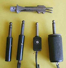
Sometime-mode male tip-sleeve connectors. The leftmost plug has three conductors; the others have two. At the height is a iii-usher console jack.

Modernistic profile 2-conductor male
1⁄4 in TS connectors
The original application for the half dozen.35 mm ( 1⁄4 in) telephone jack was in transmission telephone exchanges.[36] Many unlike configurations of these telephone plugs were used, some all-around v or more conductors, with several tip profiles. Of these many varieties, only the two-conductor version with a rounded tip profile was compatible between different manufacturers, and this was the design that was at first adopted for utilise with microphones, electric guitars, headphones, loudspeakers, and other audio equipment.
When a three-usher version of the 6.35 mm plug was introduced for use with stereo headphones, information technology was given a sharper tip contour in order to brand it possible to manufacture jacks that would accept only stereo plugs, to avoid brusque-circuiting the right channel of the amplifier. This attempt has long been abandoned, and now the convention is that all plugs fit all sockets of the same size, regardless of whether they are balanced or unbalanced, mono or stereo. Nigh 6.35 mm plugs, mono or stereo, at present accept the profile of the original stereo plug, although a few rounded mono plugs are all the same produced. The profiles of stereo miniature and sub-miniature plugs have always been identical to the mono plugs of the same size.
The results of this concrete compatibility are:
- If a two-conductor plug is inserted into a three-conductor socket, the outcome is that the band (right channel) of the socket is grounded. This belongings is deliberately used in several applications.[ specify ] However, if equipment is non designed for such a apply, grounding the right channel causes a brusk circuit which has the potential to damage an audio amplifier channel. In whatsoever instance, whatever betoken from the right channel is naturally lost in this scenario.
- If a three-conductor plug is continued to a two-usher socket, normally the effect is to exit the ring of the plug unconnected. This open up circuit is potentially dangerous to equipment utilizing vacuum tubes, just nigh solid-state devices will tolerate an open status well. A three-conductor socket could be wired as an unbalanced mono socket to footing the ring in this situation, but the more conventional wiring is to exit the ring unconnected, exactly simulating a mono socket.
Because of a lack of standardization in the by regarding the dimensions (length) given to the band usher and the insulating portions on either side of it in vi.35 mm ( i⁄4 in) phone connectors and the width of the conductors in different brands and generations of sockets, there are occasional bug with compatibility between differing brands of plug and socket. This can consequence in a contact in the socket bridging (shorting) the band and sleeve contacts on a phone connector.
General use [edit]


A three.5 mm four-conductor TRRS phone connector

A 3.5 mm 5-conductor TRRRS phone connector
In the most mutual arrangement, consequent with the original intention of the blueprint, the male plug is connected to a cable, and the female socket is mounted in a piece of equipment. A considerable variety of line plugs and panel sockets is available, including plugs suiting various cable sizes, right-angle plugs, and both plugs and sockets in a diverseness of cost ranges and with current capacities upwards to 15 amperes for certain heavy-duty 1⁄4 in versions intended for loudspeaker connections.[37]
Mutual uses of phone plugs and their matching sockets include:
- Headphone and earphone jacks on a wide range of equipment. 6.35 mm ( 1⁄4 in) plugs are common on dwelling and professional component equipment, while iii.v mm plugs are nearly universal for portable sound equipment and headphones. two.5 mm plugs are not as mutual, only are used on communication equipment such as cordless phones, mobile phones, and ii-way radios, especially in the earliest years of the 21st century before the 3.5 mm became standard on mobile phones. The use of headphone jacks in smartphones is declining as of 2020[update] in favor of USB-C connectors and wireless Bluetooth solutions.
- Consumer electronics devices such as digital cameras, camcorders, and portable DVD players use three.5 mm connectors for blended video and sound output. Typically, a TRS connexion is used for mono unbalanced audio plus video, and a TRRS connection for stereo unbalanced audio plus video. Cables designed for this apply are often terminated with RCA connectors on the other finish. Sony too used this style of connection as the Television set-Out on some models of Vaio laptop.
- Hands-free sets and headsets often utilize 3.five mm or 2.5 mm connectors. TRS connectors are used for mono sound out and an unbalanced microphone (with a shared ground). Four-conductor TRRS phone connectors add an additional audio aqueduct for stereo output. TRRS connectors used for this purpose are sometimes interoperable with TRS connectors, depending on how the contacts are used.[ commendation needed ]
- Microphone inputs on tape and cassette recorders, sometimes with remote command switching on the ring, on early, monaural cassette recorders mostly a dual-pivot version consisting of a three.5 mm TS for the microphone and a 2.v mm TS for remote control which switches the recorder's ability supply.
- Patching points (insert points) on a wide range of equipment.
- Personal computers, sometimes using a sound card plugged into the figurer. Stereo 3.5 mm jacks are used for:[b]
- Line in (stereo)
- Line out (stereo)
- Headphones and loudspeaker out (stereo)
- Microphone input (mono, commonly with v V power available on the ring.[c])
- Older laptop computers generally accept one jack for headphones and i mono jack for a microphone at microphone level.[d]
- LCD monitors with built-in speakers will demand a cable with 3.five mm male TRS plugs on each end to connect to the sound bill of fare.
- Devices designed for surround output may use multiple jacks for paired channels (eastward.thousand. TRS for front left and right; TRRS for front center, rear eye, and subwoofer; and TRS for surround left and right).[e]
- Eurorack, Moog and other modular synthesizers
- Almost all electrical guitars utilise a 1⁄iv in mono jack as their output connector. Some makes (such as Shergold) use a stereo jack instead for stereo output, or a 2nd stereo jack, in addition to a mono jack (as with Rickenbacker).
- Musical instrument amplifiers for guitars, basses and similar amplified musical instruments. one⁄4 in jacks are overwhelmingly the nigh mutual connectors for:
- Inputs. A shielded cable with a mono one⁄4 in phone plug on each end is commonly termed a guitar cablevision or a patch cable, the kickoff name reflecting this usage, the second the history of the phone plug's development for employ in transmission telephone exchanges.
- Loudspeaker outputs
- Line outputs
- Foot switches and effects pedals. Stereo plugs are used for double switches (for example by Fender). There is little compatibility between makers.
- Effects loops, which are normally wired as patch points
- Electronic keyboards use jacks for a similar range of uses to guitars and amplifiers, and in add-on:
- Sustain pedals
- Expression pedals
- Electronic drums use jacks to connect sensor pads to the synthesizer module or MIDI encoder. In this usage, a change in voltage on the wire indicates a drum stroke.
- TRS jacks are sometimes used for balanced connections for instance in meaty or economy audio mixing desks for balanced microphone inputs. In some sound equipment, a TRS connection may be offered in addition to an XLR balanced line connector.
- Loudspeaker connections for older or consumer sound reinforcement equipment. Speakon connectors are used in modern professional systems as they mate with greater contact area and thus carry higher electric current, lock in place and do not risk shorting out the amplifier upon insertion or disconnection. Some professional loudspeakers deport both Speakon and TRS connectors for compatibility. Heavy-duty 1⁄4 in loudspeaker jacks are rated at 15 A maximum which limits them to applications involving less than 1,800 watts.
- Modular synthesizers commonly utilise monophonic cables for creating patches.
- Quarter-inch phone connectors are widely used to connect external processing devices to insert points on mixing consoles. Two- or 3-conductor telephone connectors might be used in pairs as separate transport and return jacks, or a unmarried three-conductor telephone jack might serve as both send and render, in which case the signals are unbalanced. The i unbalanced combination send/render TRS insert jack saves both panel space and component complication, but the unbalanced connection may introduce a slight buzz. Insert points on mixing consoles may also be XLR, RCA or bantam TT (tiny telephone) jacks, depending on the brand and model.
- Some small electronic devices such as audio cassette players, particularly in the cheaper cost brackets, use a ii-conductor iii.five mm or two.5 mm phone jack as a DC ability connector.
- Some photographic studio strobes have i⁄4 in or iii.5 mm jacks for the flash synchronization input. A camera'due south electrical flash output (PC socket or hot shoe adapter) is cabled to the strobe light's sync input jacks.
- Some cameras use the ii.5 mm stereo jack for the connector for the remote shutter release (and focus activation); examples are Canon's RS-60E3 remote switch and Sigma's CR-21 wired remote command.
- Some miniaturized electronic devices utilize 2.5 mm or three.5 mm jacks as serial port connectors for data transfer and unit programming. This technique is particularly common on graphing calculators, such as the TI-83 series, and some types of apprentice and two-way radio. In more modern equipment USB mini-B connectors are provided in addition to or instead of jack connectors. The second-generation iPod Shuffle from Apple has one TRRS jack which serves as headphone, USB, or ability supply, depending on the connected plug.
- The Atari 2600 (Video Computer System), the start widely popular dwelling house video game console with interchangeable software programs, used a 3.v mm TS (two conductor) jack for 9 V 500 mA DC power.
- The Apple Lisa personal computer used a three-conductor TRS telephone connector for its keyboard.
- The Sangean DCR-200 radio uses a wire aeriform terminating with a 2.5 mm phone connector.
Estimator sound [edit]

three.five mm jacks for microphone, audio out, and line-level audio in

A 3.5 mm plug for computer audio

A 3.5 mm headphone socket (TRS) on a computer
Personal figurer sound cards, such as Creative Labs' Audio Blaster line, utilize a 3.5 mm telephone connector as a mono microphone input, and evangelize a 5 V bias voltage on the ring to power the FET preamplifier built into electret microphones. Adjustments may be required to achieve compatibility between different manufacturers.[38]
The Apple tree PlainTalk microphone jack used on some older Macintosh systems is designed to accept an extended three.5 mm three-conductor phone connector; in this case, the tip carries power for a preamplifier inside the microphone. It cannot accept a standard microphone without a preamp. If a PlainTalk-uniform microphone is not available, the jack tin can accept a line-level sound input.
Unremarkably, 3.five mm three-usher sockets are used in computer sound cards for stereo output. Thus, for a sound card with 5.1 output, there will be 3 sockets to accommodate six channels: front left and correct; environs left and right; and heart and subwoofer. 6.1 and 7.one channel audio cards from Creative Labs, however, use a unmarried three-usher socket (for the forepart speakers) and two four-usher sockets.[f] This is to accommodate rear-heart (6.1) or rear left and right (7.1) channels without the demand for additional sockets on the sound card.
Some portable computers have a combined 3.5 mm TRS-TOSLINK jack, supporting stereo audio output using a TRS connector, or TOSLINK (stereo or 5.1 Dolby Digital/DTS) digital output using a suitable optical adapter. Most iMac computers have this digital/analog combo output feature equally standard, with early MacBooks having ii ports, i for analog/digital audio input and other for output. Support for input was dropped on various afterward models[39] [xl]
Some newer computers, such as Lenovo laptops, take 3.5 mm TRRS headset sockets, which are compatible with telephone headsets and may be distinguished by a headset icon instead of the usual headphones or microphone icons. These are particularly used for vocalization over IP.
Video [edit]

Unlike length 3.v mm TRRS connectors
Equipment requiring video with stereo audio input or output sometimes uses three.5 mm TRRS connectors. Two incompatible variants exist, of 15 millimetres (0.59 in) and 17 mm (0.67 in) length, and using the wrong variant may either but not work, or could cause physical harm.
Attempting to fully insert the longer (17 mm) plug into a receptacle designed for the shorter (15 mm) plug may impairment the receptacle, and may damage whatsoever electronics located immediately backside the receptacle. However, partially inserting the plug volition work as the tip/band/band distances are the same for both variants.
A shorter plug in a socket designed for the longer connector may non exist retained firmly and may result in wrong signal routing or a short circuit inside the equipment (e.g. the plug tip may cause the contacts inside the receptacle – tip/ring 1, etc. - to short together).
The shorter 15 mm TRRS variant is more than common and physically uniform with standard 3.v mm TRS and TS connectors.
Recording equipment [edit]

Stereo devices which apply "plug-in power": the electret capsules are wired in this way.
Many small video cameras, laptops, recorders and other consumer devices utilise a iii.5 mm microphone connector for attaching a (mono/stereo) microphone to the arrangement. These fall into three categories:
- Devices that employ an unpowered microphone: usually a cheap dynamic or piezoelectric microphone. The microphone generates its own voltage, and needs no power.
- Devices that use a self-powered microphone: usually a condenser microphone with internal battery-powered amplifier.
- Devices that use a "plug-in powered" microphone: an electret microphone containing an internal FET amplifier. These provide a good quality indicate, in a very small microphone. Nonetheless, the internal FET needs a DC power supply, which is provided every bit a bias voltage for an internal preamp transistor.
Plug-in ability is supplied on the same line as the sound indicate, using an RC filter. The DC bias voltage supplies the FET amplifier (at a depression electric current), while the capacitor decouples the DC supply from the AC input to the recorder. Typically, 5=1.5 V, R=1 kΩ, C=47 μF.
If a recorder provides plug-in power, and the microphone does not need information technology, everything will usually work ok. In the antipodal instance (recorder provides no power; microphone needs power), no audio volition exist recorded. Neither misconfiguration will harm consumer hardware, just providing power when none is needed could destroy a circulate-type microphone.[ citation needed ]
PDAs and mobile phones [edit]

All iPhone models from the first generation to the 6S and SE (outset generation) employ a four-conductor (TRRS) phone connector (center) for a wired headset.
Three- or iv-conductor (TRS or TRRS) 2.v mm and 3.v mm sockets are common on older cell phones and newer smartphones respectively, providing mono (iii conductor) or stereo (four conductor) sound and a microphone input, together with signaling (e.g., push button a button to answer a call). These are used both for handsfree headsets (esp. mono audio plus mic, likewise stereo audio plus mic, plus signaling for call handling) and for (stereo) headphones (stereo audio, no mic). Wireless (connectorless) headsets or headphones usually utilize the Bluetooth protocol.
3.5 mm TRRS (stereo-plus-mic) sockets became particularly common on smartphones, and have been used e.g. by Nokia since 2006; they are often uniform with standard 3.5 mm stereo headphones. Some computers at present too include a TRRS headset socket, compatible with headsets intended for smartphones.
There are multiple conflicting standards for TRRS connectors and their compatibility with 3 usher TRS. The iv conductors of a TRRS connector are assigned to dissimilar purposes by different manufacturers. Whatsoever iii.5 mm plug tin exist plugged mechanically into any socket, but many combinations are electrically incompatible. For case, plugging TRRS headphones into a TRS headset socket (or vice versa) or plugging TRRS headphones from one manufacturer into a TRRS socket from another may not function correctly, or at all. Mono audio will unremarkably work, but stereo sound or microphone may not piece of work, depending on wiring. Signaling compatibility depends both on wiring compatibility and the signals sent by the hands-free/headphones controller being correctly interpreted by the telephone.[ original research? ] Adapters that are wired for headsets volition not work for stereo headphones and conversely.[ dubious ] Further, as TTY/TDDs are wired equally headsets, TTY adapters tin also connect a 2.5 mm headset to a telephone.
TRRS standards [edit]
Two different forms are frequently found, both of which place left audio on the tip and right sound on the start band (for compatibility with stereo connectors). Where they differ is in the placement of the microphone and return contacts:
The kickoff, which places the footing return on the sleeve and the microphone on the second ring, is standardized in OMTP[41] and has been accepted as a national Chinese standard YDT 1885–2009. It is by and large used on older devices, such as older Nokia mobiles, older Samsung smartphones, and some Sony Ericsson phones,[42] and products meant for the Chinese market.[43] [44] Headsets using this wiring may be indicated by blackness plastic separators between the rings.[45] [44]
The second, which reverses these contacts, with the microphone on the sleeve, is used past Apple'due south iPhone line until the 6S and SE (1st), and has go the de facto TRRS standard, to maintain compatibility with these products.[46] [47] [48] It is now used by HTC devices, recent Samsung, Nokia, and Sony phones, among others. This is referred to as CTIA/AHJ, and has the disadvantage that the mic will exist shorted to footing if the body of the device is metal and the sleeve has a flange that contacts it. Headsets using this wiring may be indicated by white plastic separators between the rings.[45] [44]
If a CTIA headset is connected to a mobile telephone with OMTP interface, the missing ground will effectively connect speakers in out-of-phase series, resulting in no voice on typical pop music recordings where the singers are in the eye; in this case, if the main microphone button is held down, shorting across the microphone and restoring footing, the correct sound may be audible.[44]
| Standard | Tip | Ring 1 | Band ii | Sleeve | Devices using this standard |
|---|---|---|---|---|---|
| CTIA, AHJ | Left audio | Right audio | Ground | Microphone | Nigh Android devices.[49] Apple tree, HTC, LG, BlackBerry, latest Nokia (including 1st generation Lumia as well every bit later models [ clarification needed ]), latest Samsung, Jolla, Microsoft (including Surface, and Xbox One controller), Sony Playstation 4 (DualShock 4[50]) |
| CTIA-manner AV[51] | Left audio | Right audio | Ground | CVBS video | Apple tree iPod (up to 6th generation), Raspberry Pi (2014 onwards), Xbox 360 E, Zune (defunct), some older mobile phones (including Nokia N93, Nokia N95,[52] Samsung Galaxy Due south GT-I9000,[53] T-Mobile Sidekick 4G) |
| OMTP | Left audio | Correct audio | Microphone | Basis | Old Nokia and as well Lumia starting from the 2d generation),[54] old Samsung (2012 Chromebooks), some onetime Sony Ericsson smartphones (2010 and 2011 Xperias),[55] Sony (PlayStation Vita), OnePlus 1. |
| OMTP-style radios | Speaker | Clone | Microphone / PTT | Ground | Yaesu FT-60R amateur radio hand-held.[56] [57] [58] |
| Video/audio one | Left audio | CVBS video | Footing | Correct audio | Sony and Panasonic camcorders. On some early Sony camcorders, this socket doubled up as a headphone socket. When a headphone plug was inserted, band two was shorted to the sleeve contact and the camcorder output the correct sound on band ane.[59] |
| Video/audio 2 | CVBS video | Left audio | Right audio | Ground | Unknown camcorders, portable VCD and DVD players, Western Digital TV live!, some newer LG TVs. |
| Video/audio 3 | CVBS video | Left audio | Basis | Correct sound | Toshiba TVs |
The 4-pole iii.five mm connector is defined by the Japanese standard JEITA/EIAJ RC-5325A, "four-Pole miniature concentric plugs and jacks", originally published in 1993.[60] iii-pole 3.five mm TRS connectors are divers in JIS C 6560. Encounter also JIS C 5401 and IEC 60130-eight.
Interoperability [edit]
The USB Type-C Cable and Connector Specification Revision 1.1 specifies a mapping from a USB-C jack to a iv-pole TRRS jack, for the employ of headsets, and supports both CTIA and OMTP (YD/T 1885–2009) modes. See Sound Adapter Accessory Mode (Appendix A). Some devices transparently handle many jack standards,[61] [62] and there are hardware implementations of this available every bit components.[63]
Some devices apply voltage to the sleeve and second ring to detect the wiring, and switch the last 2 conductors to let a device made to one standard to be used with a headset fabricated to the other.[64]
TRRRS standards [edit]
New TRRRS standard for three.five mm connectors was developed and recently canonical by ITU-T.[65] The new standard, chosen P.382 (formerly P.MMIC), outlines technical requirements and examination methods for a v-pole socket and plug configuration. Compared to the legacy TRRS standard, TRRRS provides one extra line that can be used for connecting a second microphone or external ability to/from the audio accompaniment.
P.382 requires compliant sockets and plugs to be backwards compatible with legacy TRRS and TRS connectors. Therefore, P.382 compliant TRRRS connectors should permit for seamless integration when used on new products. TRRRS connectors enable following audio applications: active racket cancelling, binaural recording and others, where dual counterpart microphone lines can be directly connected to a host device. It was unremarkably found on Sony phones starting with the Xperia Z1-XZ1 and Xperia 1 2.
Switch contacts [edit]

Miniature phone plugs and jacks. All are 3.5 mm except the gilded-plated plug, which is 2.5 mm. I of the 3.5 mm jacks is 2-conductor and the others are three usher. In this collection the tan-colored jacks have commonly-closed switches.
Panel-mounting jacks are often provided with switch contacts. Almost commonly, a mono jack is provided with one normally airtight (NC) contact, which is connected to the tip (alive) connection when no plug is in the socket, and disconnected when a plug is inserted. Stereo sockets commonly provide two such NC contacts, one for the tip (left channel alive) and ane for the band or collar (right channel live). Some designs of jack also take such a connection on the sleeve. As this contact is usually ground, it is non much apply for signal switching, merely could be used to betoken to electronic circuitry that the socket was in use.
Less commonly, some jacks are provided with normally open (NO) or change-over contacts, and/or the switch contacts may be isolated from the connector.
The original purpose of these contacts was for switching in telephone exchanges, for which there were many patterns. Two sets of change-over contacts, isolated from the connector contacts, were common. The more recent pattern of one NC contact for each indicate path, internally fastened to the connector contact, stems from their use as headphone jacks. In many amplifiers and equipment containing them, such as electronic organs, a headphone jack is provided that disconnects the loudspeakers when in apply. This is done past means of these switch contacts. In other equipment, a dummy load is provided when the headphones are not connected. This is also hands provided by means of these NC contacts.
Other uses for these contacts have been found. One is to interrupt a point path to enable other circuitry to be inserted. This is done by using ane NC contact of a stereo jack to connect the tip and ring together when no plug is inserted. The tip is so made the output, and the band the input (or vice versa), thus forming a patch point.
Some other apply is to provide culling mono or stereo output facilities on some guitars and electronic organs. This is accomplished by using two mono jacks, i for left channel and i for right, and wiring the NC contact on the right channel jack to the tip of the other, to connect the two connector tips together when the right channel output is non in use. This then mixes the signals so that the left channel jack doubles as a mono output.
Where a three.v mm or 2.5 mm jack is used as a DC power inlet connector, a switch contact may be used to disconnect an internal battery whenever an external power supply is connected, to prevent incorrect recharging of the bombardment.
A standard stereo jack is used on most battery-powered guitar effects pedals to eliminate the demand for a separate power switch. In this configuration, the internal bombardment has its negative terminal wired to the sleeve contact of the jack. When the user plugs in a two-conductor (mono) guitar or microphone atomic number 82, the resulting brusque circuit betwixt sleeve and ring connects an internal battery to the unit's circuitry, ensuring that it powers upwards or downward automatically whenever a signal lead is inserted or removed. A drawback of this design is the risk of inadvertently discharging the battery if the lead is not removed later employ, such as if the equipment is left plugged in overnight.
Design [edit]

Examples of jack configurations, oriented so the plug 'enters' from the right. The most common circuit configurations are the elementary mono and stereo jacks (A and B); however at that place are a corking number of variants manufactured.[66]
- A 2-conductor TS phone connector. The connection to the sleeve is the rectangle towards the correct, and the connexion to the tip is the line with the notch. Wiring connections are illustrated as white circles.
- A iii-usher TRS phone connector. The upper connector is the tip, as it is farther away from the sleeve. The sleeve is shown connected directly to the chassis, a very common configuration. This is the typical configuration for a balanced connexion. Some jacks have metal mounting connections (which would make this connexion) and some take plastic, to isolate the sleeve from the chassis, and provide a dissever sleeve connexion point, as in A.
- This three-usher jack has 2 isolated SPDT switches. They are activated by a plug going into the jack, which disconnects i throw and connects the other. The white arrowheads indicate a mechanical connexion, while the black arrowheads indicate an electrical connectedness. This would be useful for a device that turns on when a plug is inserted, and off otherwise, with the ability routed through the switches.
- This iii-usher jack has two commonly airtight switches connected to the contacts themselves. This would be useful for a patch point, for instance, or for allowing another signal to feed the line until a plug is inserted. The switches open when a plug is inserted. A common use for this style of connector is a stereo headphone jack that shuts off the default output (speakers) when the connector is plugged in.

- Sleeve: unremarkably ground
- Ring: Right-hand channel for stereo signals, negative polarity for balanced mono signals, power supply for ability-using mono point sources
- Tip: Left-hand channel for stereo signals, positive polarity for counterbalanced mono signals, signal line for unbalanced mono signals
- Insulating rings
| Pin | Unbalanced mono | Balanced mono in/out[67] (simplex) | Unbalanced stereo | |
|---|---|---|---|---|
| In/out (simplex) | Insert[68] | |||
| Tip | Signal | Send or return signal | Positive, hot | Left aqueduct |
| Band | Basis, or no connexion | Render or transport signal | Negative, cold | Right channel |
| Sleeve | Footing | |||
- Notes
-
- The starting time version of the popular Mackie 1604 mixer, the CR1604, used a tip negative, ring positive jack wiring scheme on the chief left and right outputs.[69] [seventy]
- Early QSC amplifiers used a tip negative, band positive input wiring scheme.[71]
- Whirlwind Line Balancer/Splitters exercise not utilise the sleeve equally a conductor on their unbalanced 6.35 mm/ 1⁄4 in TRS phone input. Tip and ring are wired to the transformer'southward 2 terminals; the sleeve is non connected.[72]
Balanced audio [edit]
When a phone connector is used to make a balanced connexion, the 2 active conductors are both used for a monaural betoken. The band, used for the right channel in stereo systems, is used instead for the inverting input. This is a common use in small audio mixing desks, where space is a premium and they offering a more compact alternative to XLR connectors. Another advantage offered by TRS telephone connectors used for balanced microphone inputs is that a standard unbalanced signal lead using a TS phone jack can simply be plugged into such an input. The ring (right channel) contact so makes contact with the plug body, correctly grounding the inverting input.
A disadvantage of using phone connectors for balanced audio connections is that the ground mates last and the socket grounds the plug tip and ring when inserting or disconnecting the plug. This causes bursts of hum, cracks and pops and may stress some outputs equally they will be short circuited briefly, or longer if the plug is left half in.
This problem does not occur when using the 'gauge B' (BPO) phone connector (PO 316)[73] which although it is of 0.25 in (half-dozen.35 mm) diameter has a smaller tip and a recessed band so that the basis contact of the socket never touches the tip or ring of the plug. This blazon was designed for balanced audio utilise, being the original telephone 'switchboard' connector and is still mutual in broadcast, telecommunications and many professional person audio applications where it is vital that permanent circuits beingness monitored (bridged) are non interrupted by the insertion or removal of connectors. This aforementioned tapered shape used in the 'gauge B' (BPO) plug tin can exist seen also in aviation and military applications on diverse diameters of jack connector including the PJ-068 and 'bantam' plugs. The more common straight-sided profile used in domestic and commercial applications and discussed in nearly of this article is known as 'gauge A'.
XLR connectors used in much professional person sound equipment mate the ground signal on pin 1 first.
Unbalanced audio [edit]
Telephone connectors with iii conductors are also ordinarily used as unbalanced audio patch points (or insert points, or simply inserts), with the output on many mixers found on the tip (left channel) and the input on the ring (right channel). This is often expressed every bit "tip ship, ring return". Other mixers have unbalanced insert points with "ring send, tip return". I reward of this system is that the switch contact within the panel socket, originally designed for other purposes, can be used to close the circuit when the patch point is not in utilise. An advantage of the tip transport patch point is that if it is used every bit an output only, a 2-usher mono phone plug correctly grounds the input. In the same fashion, apply of a "tip render" insert way allows a mono telephone plug to bring an unbalanced signal directly into the circuit, though in this case the output must exist robust enough to withstand being grounded. Combining ship and return functions via single 1⁄4 in TRS connectors in this way is seen in very many professional and semi-professional audio mixing desks, because information technology halves the infinite needed for insert jack fields which would otherwise demand 2 jacks, one for ship and ane for render. The tradeoff is that unbalanced signals are more decumbent to fizz, hum and outside interference.
In some three-conductor TRS phone inserts, the concept is extended by using specially designed phone jacks that will have a mono phone plug partly inserted to the outset click and volition then connect the tip to the signal path without breaking information technology. About standard phone connectors can also be used in this way with varying success, merely neither the switch contact nor the tip contact tin be relied upon unless the internal contacts have been designed with extra force for holding the plug tip in identify. Fifty-fifty with stronger contacts, an adventitious mechanical motility of the inserted plug can interrupt signal within the excursion. For maximum reliability, whatever usage involving get-go click or one-half-click positions will instead rewire the plug to brusque tip and band together and then insert this modified plug all the way into the jack.
The TRS tip return, ring send unbalanced insert configuration is by and large found on older mixers. This allowed for the insert jack to serve equally a standard-wired mono line input that would bypass the mic preamp. However tip transport has get the mostly accepted standard for mixer inserts since the early on-to-mid 1990s. The TRS band send configuration is still found on some compressor sidechain input jacks such as the dbx 166XL.[74]
In some very compact equipment, 3.5 mm TRS phone connectors are used as patch points.
Some sound recording devices use a three-conductor phone connector as a mono microphone input, using the tip as the signal path and the ring to connect a standby switch on the microphone.
Poor connections [edit]
Connectors that are tarnished, or that were not manufactured within tight tolerances, are prone to cause poor connections.[75] Depending upon the surface material of the connectors, tarnished ones tin be cleaned with a burnishing agent (for solid contumely contacts typical) or contact cleaner (for plated contacts).[75]
Meet too [edit]
- Assistant connector
- Coaxial power connector
Notes [edit]
- ^ 0.210 inch inside bore jacks are also found in discontinued Bell & Howell xvi mm projector speakers.[33]
- ^ Some college-finish sound cards provide a breakout panel that supports ane⁄4 in plug devices besides.
- ^ The traditional utilise of a stereo plug for a mono microphone for balanced output is incompatible with this configuration.
- ^ An attenuating cable can catechumen line level or apply a point from an XLR connector, but is non designed to record from a stereo device such as a radio or music player. Newer computers may feature a single TRRS female person jack (See § Computer sound).
- ^ Circuitry on the audio device may be used to switch betwixt traditional Line In/Line Out/Mic functions and environs output.
- ^ Creative's documentation uses the word pole instead of conductor to describe connector contacts.
References [edit]
- ^ International Library of Engineering: ... Principles of Telephony ... International Textbook Company, Scranton, PA. 1907. p. 36.
tip ring sleeve 0-1922.
- ^ Robert McLeish (2005). Radio Production. Newnes. ISBN0-240-51972-8.
- ^ Standard Reference Designations for Electrical and Electronics Parts and Equipments: IEEE 200-1975 (Reaffirmed 1988): Section 4.1.5.three. IEEE and ANSI, New York, NY. 1975.
- ^ Reference Designations for Electrical and Electronics Parts and Equipment: ASME Y14.44-2008 (Replaced IEEE 200-1975): Section 2.i.5.3. ASME, Fairfield, NJ. 2008. Archived from the original on 2010-03-13.
- ^ Gary D. Davis and Ralph Jones (1989). The Sound Reinforcement Handbook. Hal Leonard. ISBN0-88188-900-8.
- ^
- "Barrel – Audio Connectors". Digi-Key catalog.
- "Audio-Video Connectors". Mouser Electronics itemize.
- "Jacks & Plugs". Switchcraft catalog.
- "Definition of: mini-telephone connector". PC Magazine Encyclopedia.
Also called a 3.5 mm or 1/viii" connector, it is a plug and socket widely used for analog audio signals in portable devices.
- "Mini Telephone Plug Adapters". RAM Electronics online catalog.
(due east.g.) 3.5mm female stereo mini phone jack to one/iv" male Stereo phone plug Adapter
- ^
- Lewallen, Dale (1993). This Sometime PC. Ziff-Davis Press. p. 362. ISBN978-1-56276-108-0 . Retrieved September eight, 2016.
Think that audio cards utilise the smaller ane/8-inch mini-phono plug...
- "Connect your Mac to a habitation stereo, iPod, iPad, musical instruments, or speakers". Apple tree.com. Apple Inc. Retrieved September 8, 2016.
i/8-inch stereo mini-phono plug adapter.
- "Glossary". Monoprice. Retrieved September 8, 2016.
3.5 mm Plug/Jack: Likewise referred to as a 1/8 inch, auxiliary input, mini stereo, and mini phono.
- "Beckman Coulter Automatic Temperature Compensation (ATC) Probe" (PDF). Beckman Coulter. 2008. p. 1. Archived from the original (PDF) on September 16, 2016. Retrieved September eight, 2016.
The 3.5mm mini-phono plug connector of the ATC Probe plugs into the three.5mm mini-phono jack on the pH meter.
- Divine, John (September 7, 2016). "Apple'due south iPhone seven and its 10 Flashy Features Won't Movement AAPL Stock". USNews.com. U.S. News & Globe Report. Retrieved September eight, 2016.
...instead of the headphone jack.... There will exist a lightning-to-mini phono adapter included besides.
- Lewallen, Dale (1993). This Sometime PC. Ziff-Davis Press. p. 362. ISBN978-1-56276-108-0 . Retrieved September eight, 2016.
- ^ a b "Birthplace of the Telephone".
- ^ Frank Lewis Dyer. Edison: His Life And Inventions, p. 71.
- ^ "When Phone Operators Were Unruly Teenage Boys". 19 September 2014. Retrieved 2017-10-25 .
- ^ "Chapter 3 Local Manual Systems" (PDF).
- ^ "Showtime Commercial Telephone Exchange – Today in History: Jan 28". 28 January 2020.
- ^ "A Brief History of the Phone".
- ^ "US Patent 293,198: Telephone Switch".
- ^ Chapuis, Robert J. (2003). 100 Years of Telephone Switching. Amsterdam, The netherlands: IOS Press. p. 51. ISBN9784274906114.
- ^ "U.S. Patent 262,701: Circuits for multiple switch boards of phone exchanges".
- ^ "U.S. Patent 305,021, September 1884".
- ^ Scribner, C. Eastward. "U.S. Patent 489,570: Spring Jack Switch".
- ^ "Telephone switchboard-plug. The states 711556 A".
- ^ "Western Electric Telephonic Apparatus and Supplies (1907)".
- ^ "MIL-DTL-642/5B". 3 March 2021.
- ^ "MIL-DTL-642F: Plugs, Telephone, and Accompaniment Screws" (PDF).
- ^ "All-right jack: Simple but effective plug-in has endured for more than a century". Retrieved 2016-09-11 .
- ^ "Sony history 1960s". Sony official website.
- ^ Clarification of iii.5 mm earphone jack in described model: "Vintage Sony 1960'Southward EFM-117J Radio". WorthPoint . Retrieved 2016-01-25 .
- ^ 3.5 mm Stereo Plug, CUI Devices, retrieved 2021-09-01
- ^ "3.v mm Headset: Accompaniment Specification". Android Open Source Project . Retrieved 2019-06-15 .
- ^ "Build a Data Cable for the Yaesu VX-six".
- ^ "Geek Out V2+ User Manual".
- ^ Chinn, Howard (July 1947). "Single Jacks for Circulate Application" (PDF). Audio Engineering. 31 (6).
- ^ a b "The Depression-downward On Analogue Interfacing -". www.soundonsound.com . Retrieved 16 August 2018.
- ^ Gibson, Pecker. (2007) The Ultimate Live Sound Operator'south Handbook, p. 202. Hal Leonard Corporation. ISBN 1-4234-1971-5
- ^ "Switchcraft Phone Jack and Telephone Plug Mating Chart" (PDF). Archived from the original (PDF) on 2014-04-13. Retrieved 2013-06-24 .
- ^ "PL-55". Radionerds.com . Retrieved 17 August 2018.
- ^ "Detail # TP-120, Telephone Plug". Amphenol Nexus Technologies, Inc. Retrieved 2012-01-12 .
- ^ Ranjan Parekh; Ranjan (2006). Principles of Multimedia. Tata McGraw-Colina Educational activity. pp. 225–. ISBN978-0-07-058833-2.
- ^ "Switchcraft Z15J 1/4" Loftier Power Speaker Jack". Total Compass. Retrieved Oct 24, 2011.
High power 2-conductor speaker jack carries 15A (continuous) audio speaker current levels.
- ^ "Calculator microphones". Retrieved 2021-12-11 .
- ^ "Questions Answered iv: Optical Output on the Mac". [ permanent dead link ]
- ^ "Audio input/output on Macbook computers.". [ self-published source? ]
- ^ "Wired Analogue Audio" (PDF) . Retrieved 2012-06-01 .
- ^ "MEElectronics – P version headset earphone compatibility". Meelec.com. Archived from the original on 2010-12-27. Retrieved 2013-07-14 .
- ^ "iphone - Why practice Chinese EarPods not work with German MacBook Pro?". Ask Different . Retrieved 2020-04-24 .
- ^ a b c d "Linx:What is your mobile phone headset jack standard: OMTP or CTIA?-Headset OEM|Earphone Factory|Headphone Supplier —Mainland china LINX CO,.LTD". www.headphonefactory.cyberspace . Retrieved 2020-04-24 .
In order to fit the Chinese national conditions, Apple China released Earpods with some changes, specifically for the Chinese market place, to brand it in line with the Chinese domestic OMTP standard. ... Therefore, iPhone original headsets sod in Prc are unlike from Earpods sold in other regions.
- ^ a b "IPhone国行耳机不兼容问题 - Apple 社区". discussionschinese.apple.com . Retrieved 2020-04-24 .
- ^ "Headphone inline controls – how they differ on Apple iOS vs. Android/Nokia | Hacker News". news.ycombinator.com . Retrieved 2020-04-24 .
- ^ "Xiaomi In-Ear Headphones Pro HD (2 +1 Hybrid)". Headphone Reviews and Discussion - Head-Fi.org . Retrieved 2020-04-24 .
- ^ "Smartphone Headset Standards: Apple iPhone, AHJ (CTIA), & OMTP". Headset Buddy Aid . Retrieved 2020-04-24 .
- ^ "3.5 mm Headset Jack: Device Specification".
- ^ "Smartphone Headset Standards: Apple iPhone, AHJ (CTIA), & OMTP". Retrieved fifteen August 2021.
- ^ www.cablechick.com.au. "Agreement TRRS and Sound Jacks – Cable Chick Blog". world wide web.cablechick.com.au . Retrieved 16 August 2018.
- ^ "TV Out on the Nokia N95". All About Symbian . Retrieved 6 October 2019.
- ^ "Singtel Group, get-go in the world to launch breakthrough Android ii.1 Samsung Milky way Due south". singtel.com . Retrieved 6 October 2019.
- ^ "Jays AB headset for Windows Telephone and a note on headset standards". Allaboutwindowsphone.com . Retrieved 26 March 2017.
- ^ "2012 Xperia range uses dissimilar 3.5mm headset standard | Xperia Web log". www.xperiablog.internet. 27 February 2012. Retrieved 2017-08-17 .
- ^ Yaesu FT-60R Technical Supplement (PDF). VERTEX STANDARD CO., LTD. 2005. pp. x, xiii.
- ^ "Radio Wiring - ArgentWiki". wiki.argentdata.com . Retrieved 2020-05-29 .
- ^ "MH-37A4B wiring diagram". world wide web.qsl.net . Retrieved 2020-05-29 .
- ^ Sony and Panasonic camcorder service manuals
- ^ "EIAJ RC-5325A".
- ^ FAQ – What blazon of wired headsets can I utilise with my Nokia Lumia phone? – "Nokia Lumia 820 and 920 support both American Headset Jack (AHJ) headsets and standard Nokia OMTP headsets."
- ^ Jays AB headset for Windows Telephone and a note on headset standards – "Nokia'southward Windows Phone eight devices (Nokia Lumia 520, 521, 620, 720, 810, 820, 822, 920, 925, and 928) use a new universal connector, enabling the use of both AHJ and OMTP headsets."
- ^ "TS3A227E Autonomous Audio Accessory Detection and Configuration Switch".
- ^ Digital Silence (earphone manufacturer): caption of TRRS connectors and availability of adapter.
- ^ "ITU-T Work Plan". Retrieved 26 March 2017.
- ^ "Jack Schematics table" (PDF).
- ^ "Ofttimes Asked Questions". Retrieved 2012-05-28 .
- ^ "Diagrams" (PDF) . Retrieved 2012-05-28 .
- ^ Sweetwater (2000-01-thirteen). "Sweetwater inSync". Sweetwater.com. Retrieved 2013-07-14 .
- ^ "Silent Mode's recording tricks- Mackie CR-1604 mixer". Silentway.com. Retrieved 2013-07-14 .
- ^ "QSC Audio Products. Frequently Asked Questions".
- ^ [1] Archived Nov x, 2006, at the Wayback Machine
- ^ "Neutrik mil-b-guess-type plugs".
- ^ "dbx 166XL compressor with counterbalanced TRS tip send input and output jacks and ane TRS ring ship sidechain jack".
- ^ a b "Q. What'due south wrong with my patchbay? -". www.soundonsound.com.
External links [edit]
- The 19th Century plug that'southward still existence used—BBC News
- "The Rise and Autumn of the Headphone Jack". CNBC. 2019-08-28. Archived from the original on 2021-11-04.

Source: https://en.wikipedia.org/wiki/Phone_connector_(audio)
Posted by: williamsfiverand.blogspot.com
0 Response to "How To Clean 1/4 Inch Trs Contacts"
Post a Comment